


No products in the cart.

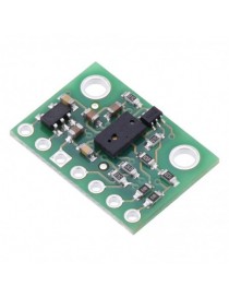
This sensor is a carrier/breakout board for ST’s VL6180X proximity and ambient light sensor, which measures the range to a target object up to 20 cm away (or 60 cm with reduced resolution). The VL6180X uses time-of-flight measurements of infrared pulses for ranging, allowing it to give accurate results independent of the target’s color and surface. Distance and ambient light level measurements can be read through a digital I²C interface. The board has a 2.8 V linear regulator and integrated level-shifters that allow it to work over an input voltage range of 2.7 V to 5.5 V, and the 0.1? pin spacing makes it easy to use with standard solderless breadboards and 0.1? perfboards.
Overview
The VL6180X from ST Microelectronics is a sensor that combines proximity ranging and ambient light level measurement capabilities into a single package. This board is a carrier for the VL6180X, so we recommend careful reading of the VL6180X datasheet (2MB pdf) before using this product.
Unlike simpler optical sensors that use the intensity of reflected light to detect objects, the VL6180 uses ST’s FlightSense technology to precisely measure how long it takes for emitted pulses of infrared laser light to reach the nearest object and be reflected back to a detector, making it essentially a short-range lidar sensor. This time-of-flight (TOF) measurement enables it to accurately determine the absolute distance to a target with 1 mm resolution, without the object’s reflectance influencing the measurement. The sensor is rated to perform ranging measurements of up to 10 cm (4?), but it can often provide readings up to 20 cm (8?) with its default settings. Furthermore, the VL6180X can be configured to measure ranges of up to 60 cm (24?) at the cost of reduced resolution, although successful ranging at these longer distances will depend heavily on the target and environment. (For more information, see “Range scaling factor” below.)
The VL6180 also includes an ambient light sensor, or ALS, that can measure the intensity of light with which it is illuminated. Ranging and ambient light measurements are available through the sensor’s I²C (TWI) interface, which is also used to configure sensor settings, and two independently-programmable GPIO pins can be configured as interrupt outputs.
The VL6180X is a great IC, but its small, leadless, LGA package makes it difficult for the typical student or hobbyist to use. It also operates at voltages below 3 V, which can make interfacing difficult for microcontrollers operating at 3.3 V or 5 V. Our breakout board addresses these issues, making it easier to get started using the sensor, while keeping the overall size as small as possible.
|
VL6180X datasheet graph of typical ranging performance. |
|---|
A 1×7 strip of 0.1? header pins and a 1×7 strip of 0.1? right-angle header pins are included, as shown in the picture below. You can solder the header strip of your choice to the board for use with custom cables or solderless breadboards, or you can solder wires directly to the board itself for more compact installations.
|
|
The board has two mounting holes spaced 0.5? apart that work with #2 and M2 screws (not included).
A minimum of four connections is necessary to use the VL6180X board: VIN, GND, SCL, and SDA. The VIN pin should be connected to a 2.7 V to 5.5 V source, and GND should be connected to 0 volts. An on-board linear voltage regulator converts VIN to a 2.8 V supply for the VL6180X IC.
The I²C pins, SCL and SDA, are connected to built-in level-shifters that make them safe to use at voltages over 2.8 V; they should be connected to an I²C bus operating at the same logic level as VIN.
The two GPIO pins are open-drain outputs pulled up to 2.8 V by the board (although GPIO0 defaults to being a chip enable input). They are not connected to level-shifters on the board and are not 5V-tolerant, but they are usable as-is with many 3.3 V and 5 V microcontrollers: the microcontroller can read the sensor’s output as long as its logic high threshold is below 2.8 V, and the microcontroller can alternate its own output between low and high-impedance states to drive the pin. Alternatively, our 4-channel bidirectional logic level shifter can be used externally with those pins.
| PIN | Description |
|---|---|
| VDD | Regulated 2.8 V output. Almost 150 mA is available to power external components. (If you want to bypass the internal regulator, you can instead use this pin as a 2.8 V input with VIN disconnected.) |
| VIN | This is the main 2.7 V to 5.5 V power supply connection. The SCL and SDA level shifters pull the I²C lines high to this level. |
| GND | The ground (0 V) connection for your power supply. Your I²C control source must also share a common ground with this board. |
| SDA | Level-shifted I²C data line: HIGH is VIN, LOW is 0 V |
| SCL | Level-shifted I²C clock line: HIGH is VIN, LOW is 0 V |
| GPIO0/CE | This pin is configured as a chip enable input on power-up of the VL6180X; the board pulls it up to VDD to enable the sensor by default. Driving this pin low puts the sensor into hardware standby. After the VL6180X powers up, this pin can be reconfigured as a programmable interrupt output (VDD logic level). This input/output is not level-shifted. |
| GPIO1 | Programmable interrupt output (VDD logic level). The VL6180X also drives this pin low when it is in hardware standby. This output is not level-shifted. |

This sensor is a carrier/breakout board for ST’s VL6180X proximity and ambient light sensor, which measures the range to a target object up to 20 cm away (or 60 cm with reduced resolution). The VL6180X uses time-of-flight measurements of infrared pulses for ranging, allowing it to give accurate results independent of the target’s color and surface. Distance and ambient light level measurements can be read through a digital I²C interface. The board has a 2.8 V linear regulator and integrated level-shifters that allow it to work over an input voltage range of 2.7 V to 5.5 V, and the 0.1? pin spacing makes it easy to use with standard solderless breadboards and 0.1? perfboards.