

No products in the cart.

172:1 Metal Gearmotor 25Dx56L mm LP 12V
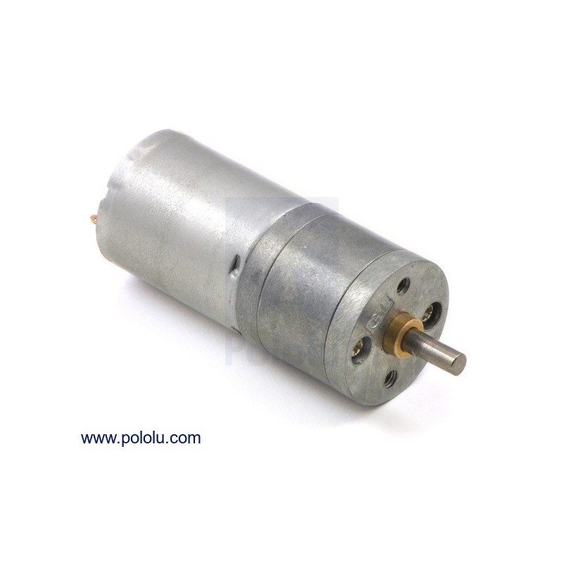
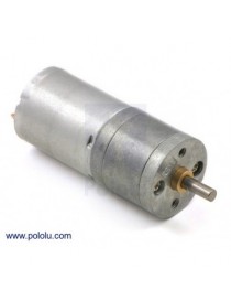
This gearmotor consists of a low-power, 12 V brushed DC motor combined with a 171.79:1
metal spur gearbox. The gearmotor is cylindrical, with a diameter just
under 25 mm, and the D-shaped output shaft is 4 mm in diameter and
extends 12.5 mm from the face plate of the gearbox.
Key specs at 12 V: 31 RPM and 100 mA (max) free-run, 180 oz-in (13 kg-cm) and 1.1 A stall.
In general, these kinds of motors can run at voltages above and below their nominal voltages; lower voltages might not be practical, and higher voltages could start negatively affecting the life of the motor.
Exact gear ratio: 22×20×22×22×22×22×2412×12×10×10×10×10×10≈171.79:1
The diagram below shows the dimensions of the 25D mm line of gearmotors (units are mm over [inches]). This diagram is also available as a downloadable PDF (223k pdf).
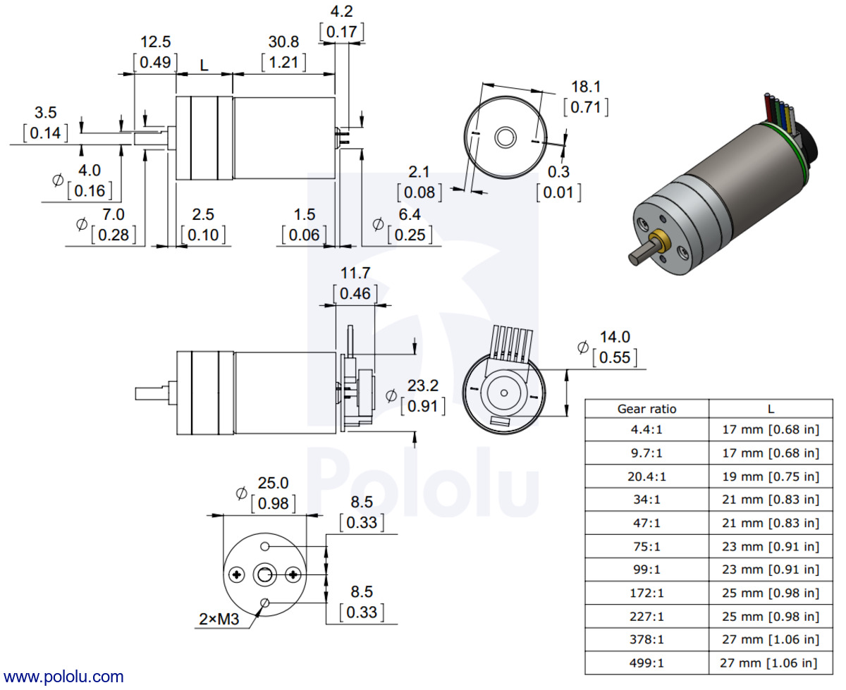 |
Dimensions of the Pololu 25D mm metal gearmotors. Units are mm over [inches]. |
|---|
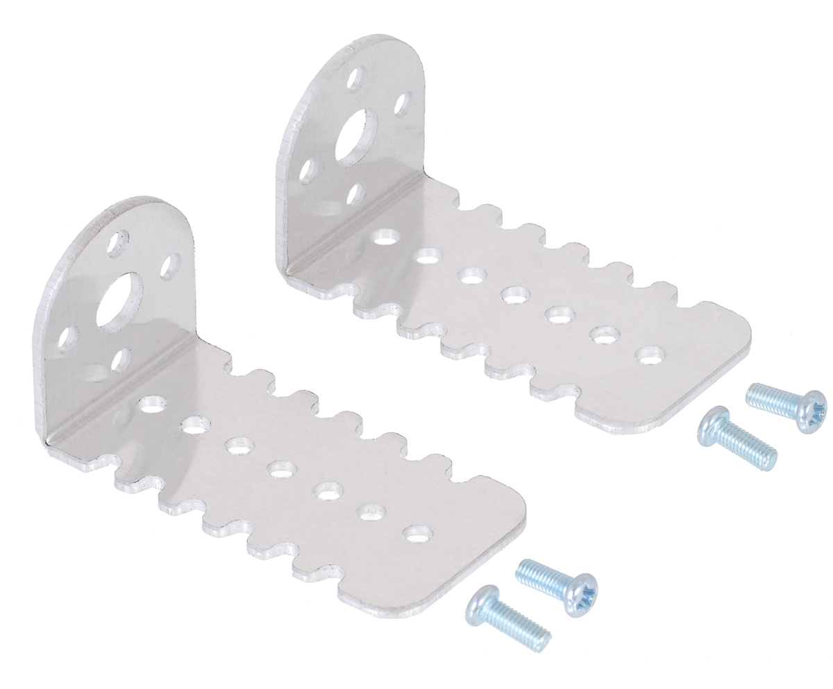
Warning: Do not screw too far into the mounting holes as the screws can hit the gears. We recommend screwing no further than 2mm (0.08″) into the screw hole.
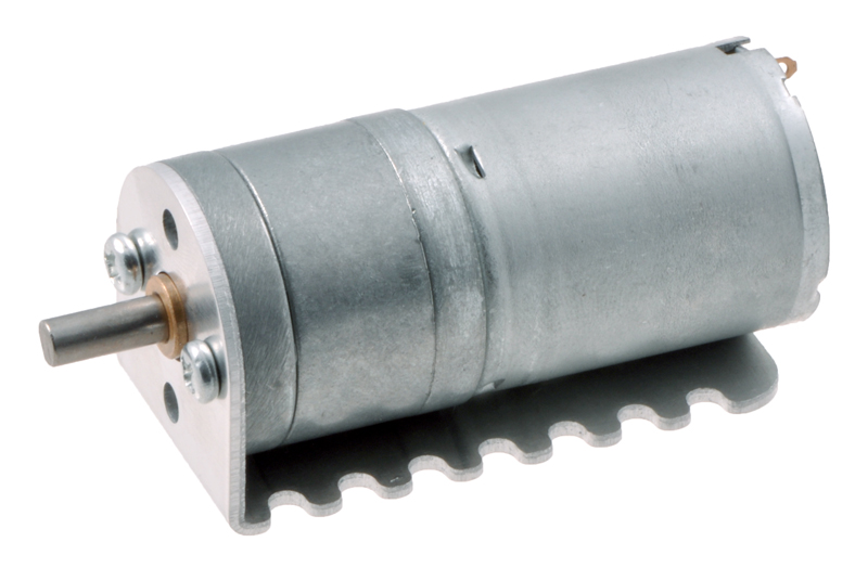
The face plate has two mounting holes threaded for M3 screws. You can use our custom-designed 25D mm metal gearmotor bracket (shown in the picture below) to mount the gearmotor to your project via these mounting holes and the screws that come with the bracket.
|
|
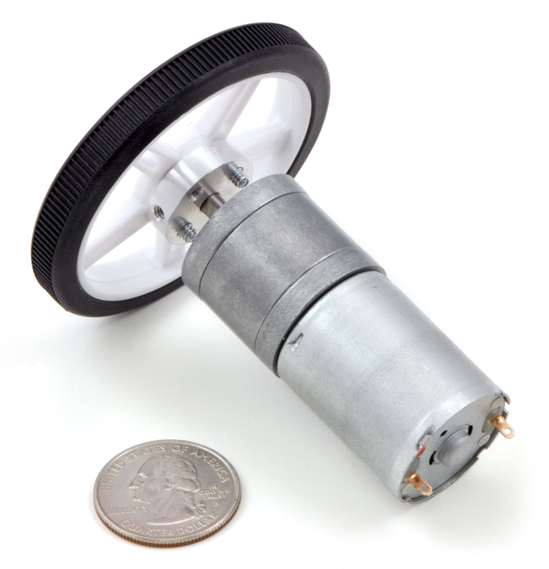
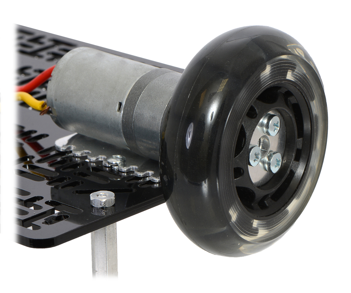
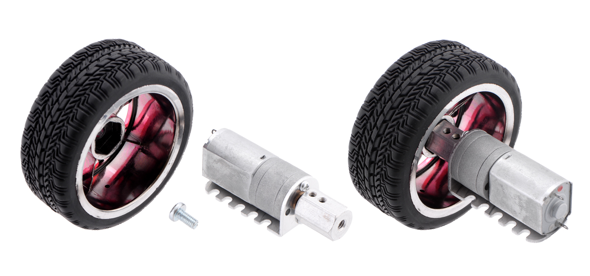
The 4 mm diameter gearbox output shaft works with Pololu universal aluminum mounting hub for 4mm shafts, which can be used to mount our larger Pololu wheels (60mm-, 70mm-, 80mm-, and 90mm-diameter) or custom wheels and mechanisms to the gearmotor’s output shaft as shown in the left picture below. Alternatively, you could use our 4mm scooter wheel adapter to mount many common scooter, skateboard, and inline skate wheels to the gearmotor’s output shaft as shown in the right picture below.
|
|
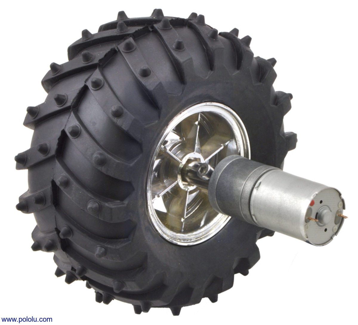
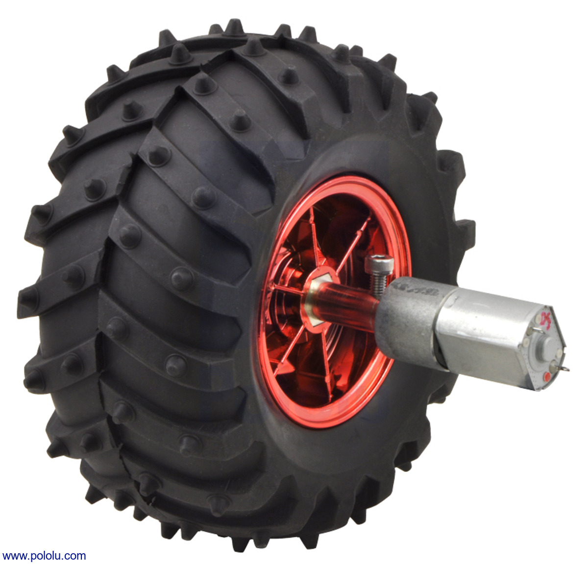
These are the same type of motors used in the Wild Thumper all-terrain chassis, so the gearbox’s output shaft also works directly with the hex adapters included with the 120mm-diameter Wild Thumper wheels (the left picture below shows a 25D mm gearmotor while the right picture shows the smaller 20D mm gearmotor):
|
|
 |
12mm Hex Wheel Adapter for 4mm Shaft on a 20D mm Metal Gearmotor. |
|---|
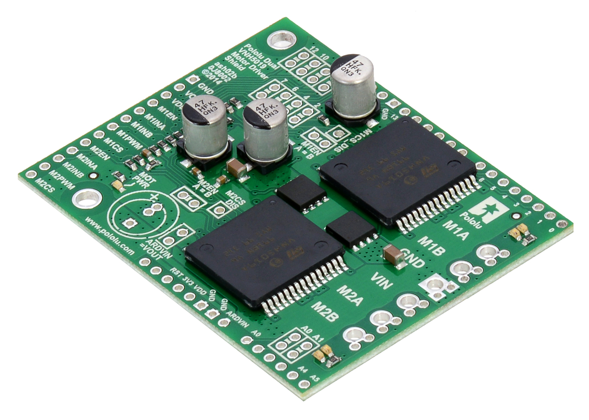
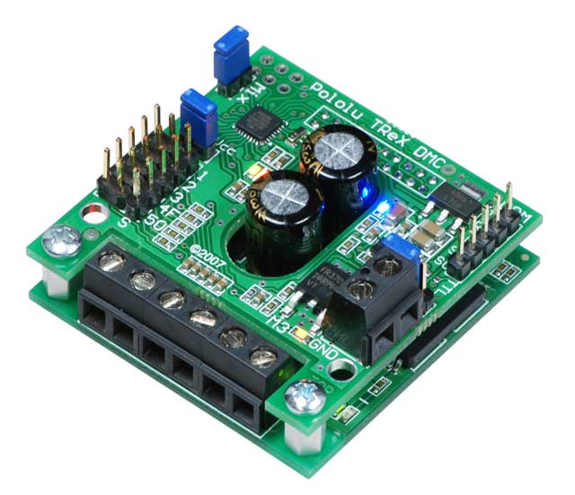
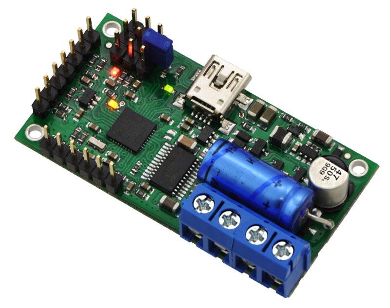
We have a number of motor controllers and motor drivers that work with these 25D mm metal gearmotors. For the LP and MP versions, we recommend our MC33296-based motor drivers, for which we have basic single and dual carriers and a dual-channel shield for Arduino. For the HP versions, we recommend our VNH5019-based motor drivers (available as single and dual carriers), though these can also be a good choice for the lower-power motors because they will run much cooler than the MC33926 carriers. If you are looking for higher-level control interfaces, such as USB, RC, analog voltages, or TTL serial, consider our Simple Motor Controllers, Jrk motor controllers, or TReX motor controllers; these controllers are available in various power levels, and the appropriate one depends on the particular version of 25D mm motor you have (we generally recommend a motor controller that can handle continuous currents above the stall current of your motor).
|
|
|
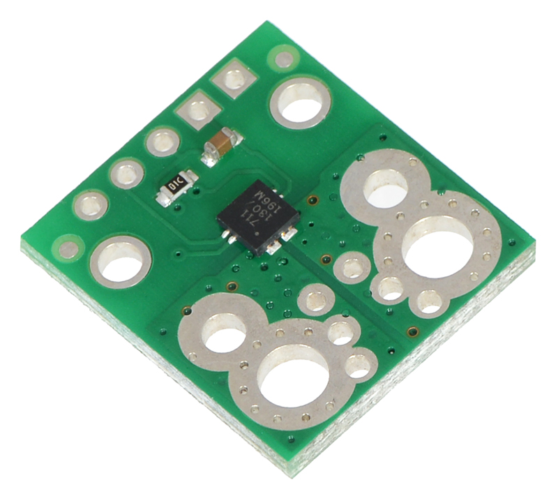
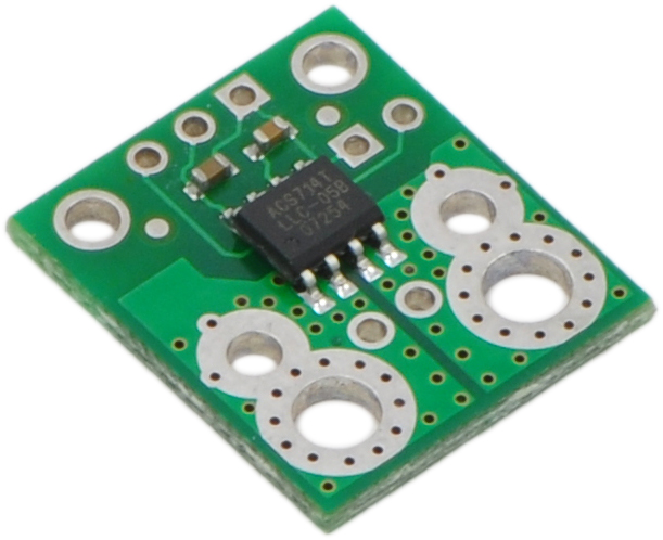
We have an assortment of Hall effect-based current sensors to choose from for those who need to monitor motor current:
|
|
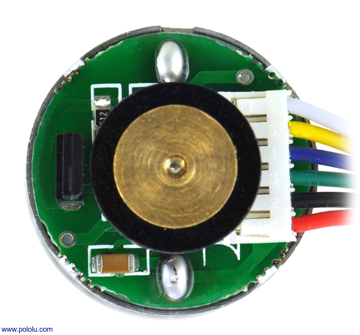 |
25D mm metal gearmotor with 48 CPR encoder: close-up view of encoder. |
|---|
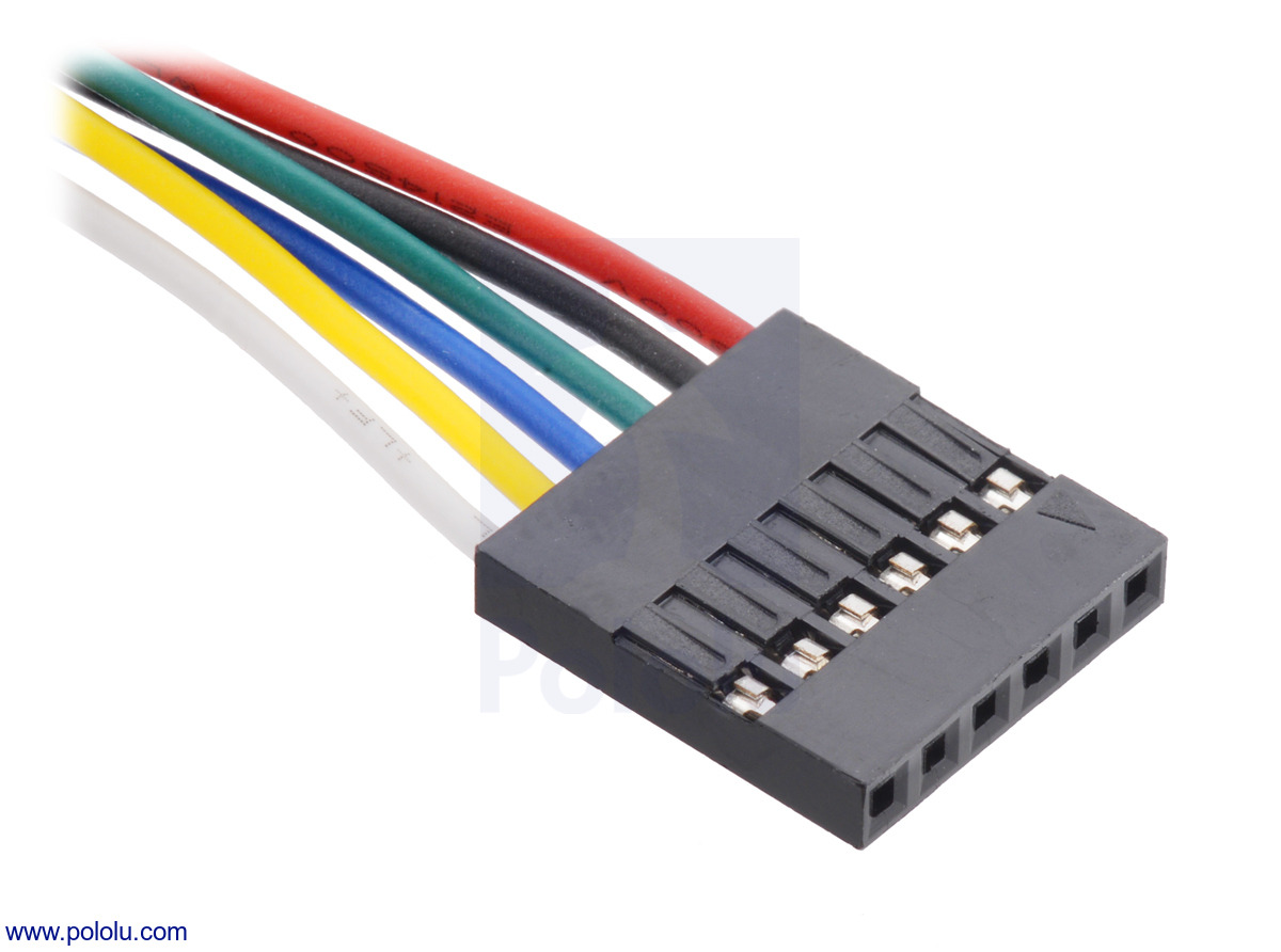 |
The versions of these gearmotors with encoders use a A two-channel Hall effect sensor to detect the rotation of a magnetic disk on a rear protrusion of the motor shaft. The quadrature encoder provides a resolution of 48 counts per revolution of the motor shaft when counting both edges of both channels. To compute the counts per revolution of the gearbox output, multiply the gear ratio by 48. The motor/encoder has six color-coded, 8″ (20 cm) leads terminated by a 1×6 female header with a 0.1″ pitch, as shown in the main product picture. This header works with standard 0.1″ male headers and our male jumper and precrimped wires. If this header is not convenient for your application, you can pull the crimped wires out of the header or cut the header off. The following table describes the wire functions:
| Color | Function |
|---|---|
| Red | motor power (connects to one motor terminal) |
| Black | motor power (connects to the other motor terminal) |
| Green | encoder GND |
| Blue | encoder Vcc (3.5 – 20 V) |
| Yellow | encoder A output |
| White | encoder B output |
The Hall sensor requires an input voltage, Vcc, between 3.5 and 20 V and draws a maximum of 10 mA. The A and B outputs are square waves from 0 V to Vcc approximately 90° out of phase. The frequency of the transitions tells you the speed of the motor, and the order of the transitions tells you the direction. The following oscilloscope capture shows the A and B (yellow and white) encoder outputs using a motor voltage of 6 V and a Hall sensor Vcc of 5 V:
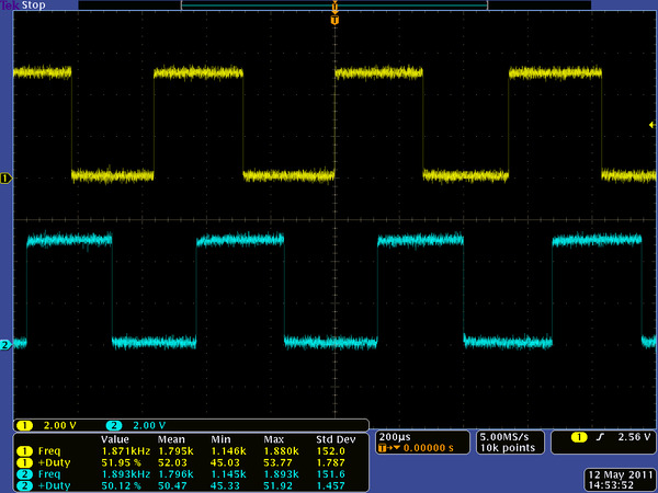 |
Encoder A and B outputs for 25D mm HP 6V metal gearmotor with 48 CPR encoder (motor running at 6 V). |
|---|
By counting both the rising and falling edges of both the A and B outputs, it is possible to get 48 counts per revolution of the motor shaft. Using just a single edge of one channel results in 12 counts per revolution of the motor shaft, so the frequency of the A output in the above oscilloscope capture is 12 times the motor rotation frequency.

172:1 Metal Gearmotor 25Dx56L mm LP 12V
This gearmotor consists of a low-power, 12 V brushed DC motor combined with a 171.79:1
metal spur gearbox. The gearmotor is cylindrical, with a diameter just
under 25 mm, and the D-shaped output shaft is 4 mm in diameter and
extends 12.5 mm from the face plate of the gearbox.
Key specs at 12 V: 31 RPM and 100 mA (max) free-run, 180 oz-in (13 kg-cm) and 1.1 A stall.