


No products in the cart.

Concentric LACT4P-12V-5 Linear Actuator with Feedback: 4" Stroke, 12V, 1.7"/s
"
The LD Series of linear actuators by Concentric International (formerly Iowa Export-Import) are 12V DC gearmotors that use a worm drive to move a shaft back and forth along its length. The worm drive ensures that the shaft will hold its position even when unpowered. Two limits switches safely stop the motor at either end of its range, while integrated diodes allow it to reverse direction after reaching a limit point if the supplied voltage is reversed. The actuators are mostly metal, and the entire case is sealed to protect against dust and water (rated IP63).
|
Connecting the bracket to one end of a Concentric LD linear actuator. |
|---|
The Concentric LD series linear actuators are available in a variety of lengths and with optional potentiometers that are linked to the shaft position, for use in feedback systems. Several lengths are also available in two gear ratios: 5:1 and 20:1. The 5:1 versions have lower load ratings—34 lbs dynamic, 450 lbs static—but allow for higher speeds, up to 1.7 in/s. The 20:1 versions are slower—up to 0.5 in/s—but are rated for dynamic loads up to 110 lbs and static loads up to 500 lbs.
| Stroke length | 20:1 | 20:1 w/feedback | 5:1 | 5:1 w/feedback |
|---|---|---|---|---|
| 2? | LACT2-12V-20 | LACT2P-12V-20 | ||
| 4? | LACT4-12V-20 | LACT4P-12V-20 | LACT4-12V-5 | LACT4P-12V-5 |
| 6? | LACT6-12V-20 | LACT6P-12V-20 | ||
| 8? | LACT8-12V-20 | LACT8P-12V-20 | ||
| 10? | LACT10-12V-20 | LACT10P-12V-20 | ||
| 12? | LACT12-12V-20 | LACT12P-12V-20 | LACT12-12V-5 | LACT12P-12V-5 |
Mounting brackets are available for attaching the actuators to a structure; two are required for each actuator.
|
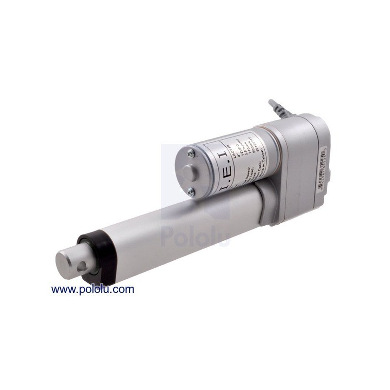
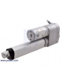
Concentric linear actuator with feedback, 4"" Stroke (LACT4P), shaft fully extended. |
|---|
Actuators with feedback have a 24? (60 cm) cable that is terminated with special female connectors as shown in the left picture below, one for the three potentiometer leads and another for the two power leads. These connectors match male versions on the extension cable for LD linear actuators. Actuator versions without feedback have a 36? (90 cm) cable with two unterminated, stripped power leads as shown in the right picture below. Linear actuators without feedback do not have cables that are compatible with the linear actuator extension cable.
|
|
The feedback feature included with our jrk motor controllers make them a great solution for precisely controlling our linear actuators with feedback. Our settings file for the jrk configuration utility makes setup easy, eliminating the need to calibrate the feedback and tune the PID constants. To get started, follow the steps below:
|
Connecting a linear actuator with feedback to a jrk 21v3 motor controller. |
|---|
While this setting file gives precise control over most of an actuator’s range, you might find decreased performance very near the extremes due to the limit switches. If your project requires better control near the actuator’s limits, you might need to recalibrate the feedback settings for your particular actuator.
| Stroke: | 4 in |
|---|---|
| Weight: | 45 oz |
| Gear ratio: | 5:1 |
|---|---|
| Free-run current @ 12V: | 500 mA |
| Stall current @ 12V: | 10 A |
| Linear speed @ 12V: | 1.7 in/s |
| Linear force @ 12V: | 34 lb1 |
| Maximum duty cycle: | 25%2 |
| Feedback potentiometer included?: | Y |
"

Concentric LACT4P-12V-5 Linear Actuator with Feedback: 4" Stroke, 12V, 1.7"/s