


No products in the cart.

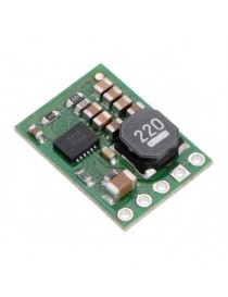
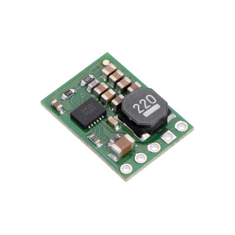
Pololu 5V, 1A Step-Down Voltage Regulator D24V10F5
"
The D24V10Fx family of step-down voltage regulators features the Intersil ISL85410 1A synchronous buck regulator and generates lower output voltages from input voltages as high as 36 V. They are switching regulators (also called switched-mode power supplies (SMPS) or DC-to-DC converters) with typical efficiencies between 80% and 93%, which is much more efficient than linear voltage regulators, especially when the difference between the input and output voltage is large. These regulators have a power-save mode that activates at light loads and a low quiescent (no load) current draw, which make them well suited for applications that are run from a battery. These regulators are available in five different fixed output voltages:
Select options:
The different versions of this regulator all look very similar, so the bottom silkscreen includes a blank space where you can add your own distinguishing marks or labels. This product page applies to all five versions of the D24V10Fx family.
The SHDN pin can be used to put the board in a low-power state that reduces the quiescent current to approximately 10 µA to 20 µA per volt on VIN, and a PG (power good) output can be used to monitor the state of the regulator’s output voltage.
The regulators feature short-circuit/over-current protection, and thermal shutdown helps prevent damage from overheating. The boards do not have reverse-voltage protection.
If you do not need quite as much current, consider the very similar D24V5Fx family of step-down voltage regulators, which can deliver up to 500 mA in a wide range of output voltages:
Select options:
The picture on the right shows a 1 A D24V10Fx regulator next to a 0.5 A D24V5Fx regulator and a common 7805 linear regulator in a TO-220 package.
The efficiency of a voltage regulator, defined as (Power out)/(Power in), is an important measure of its performance, especially when battery life or heat are concerns. This family of switching regulators typically has an efficiency of 80% to 93%, though the actual efficiency in a given system depends on input voltage, output voltage, and output current. See the efficiency graph near the bottom of this page for more information.
In order to achieve a high efficiency at low loads, this regulator automatically goes into a power-save mode where the switching frequency is reduced. In power-save mode, the switching frequency of the regulator changes as necessary to minimize power loss. This could make it harder to filter out noise on the output caused by switching.
The dropout voltage of a step-down regulator is the minimum amount by which the input voltage must exceed the regulator’s target output voltage in order to ensure the target output can be achieved. For example, if a 5 V regulator has a 1 V dropout voltage, the input must be at least 6 V to ensure the output is the full 5 V. Generally speaking, the dropout voltage increases as the output current increases. See the “Details” section below for more information on the dropout voltage for this specific regulator version.
The graphs below show the typical efficiency and dropout voltage of the 5 V D24V10F5 regulator as a function of the output current:
During normal operation, this product can get hot enough to burn you. Take care when handling this product or other components connected to it.
|
Schematic diagram for the Pololu D24V10Fx family of 1 A step-down voltage regulators. |
|---|
This schematic is also available as a downloadable pdf (173k pdf).
When connecting voltage to electronic circuits, the initial rush of current can cause voltage spikes that are much higher than the input voltage. If these spikes exceed the regulator’s maximum voltage (36 V), the regulator can be destroyed. In our tests with typical power leads (~30? test clips), input voltages above 20 V caused spikes over 36 V.
If you are connecting more than 20 V or your power leads or supply has high inductance, we recommend soldering a 33 ?F or larger electrolytic capacitor close to the regulator between VIN and GND. The capacitor should be rated for at least 50 V.
More information about LC spikes can be found in our application note, Understanding Destructive LC Voltage Spikes.
"

Pololu 5V, 1A Step-Down Voltage Regulator D24V10F5