


No products in the cart.


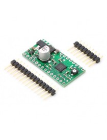
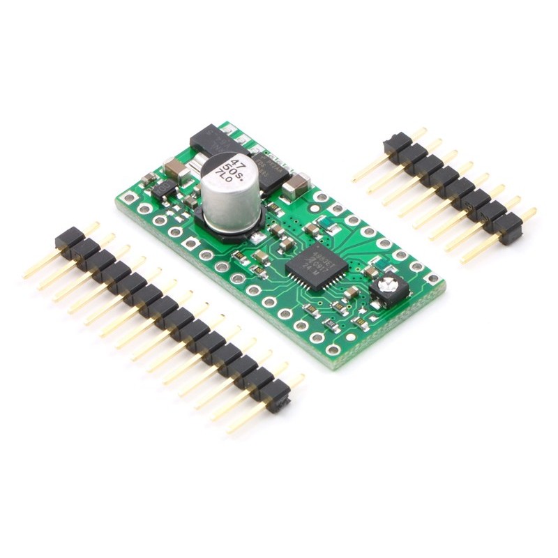
A4988 Stepper Motor Driver Carrier with Voltage Regulators
"
This product is a carrier board or breakout board for Allegro’s A4988 DMOS Microstepping Driver with Translator and Overcurrent Protection; we therefore recommend careful reading of the A4988 datasheet (1MB pdf) before using this product. This stepper motor driver lets you control one bipolar stepper motor at up to 2 A output current per coil (see the Power Dissipation Considerations section below for more information). Here are some of the driver’s key features:
This carrier has reverse power protection on the main power input and built-in 5 V and 3.3 V voltage regulators that eliminate the need for separate logic and motor supplies and let you control the driver with microcontrollers powered at 5 V or 3.3 V. We also sell a smaller, higher-performace version of the A4988 carrier without voltage regulators.
Like nearly all our other carrier boards, this product ships with all surface-mount components—including the A4988 driver IC—installed as shown in the product picture.
Some unipolar stepper motors (e.g. those with six or eight leads) can be controlled by this driver as bipolar stepper motors. For more information, please see the frequently asked questions. Unipolar motors with five leads cannot be used with this driver.
The A4988 stepper motor driver carrier with voltage regulators comes with 0.1? male header pins that can be broken into smaller strips and soldered in for use with solderless breadboards or 0.1? female connectors. You can also solder your motor leads and other connections directly to the board.
| Minimal wiring diagram for wiring a 5V microcontroller to an A4983/A4988 stepper motor driver carrier with voltage regulators (full-step mode). |
|---|
The driver requires a logic supply voltage (3 – 5.5 V) to be connected across the VDD and GND pins and a motor supply voltage (8 – 35 V) to be connected across VMOT and GND. The logic voltage can be supplied from an external source, such as that powering the logic of the rest of the system, or by jumpering the output of the 5 V or 3.3 V voltage regulator outputs to VDD. There are also surface-mount pads that allow VDD selection to be made by making a solder bridge across the appropriate pads. Note that the driver’s regulators can also be used to power other electronics in the system, such as the controlling MCU.
The motor power supply should be capable of delivering the expected currents for the stepper motors being used (peaks up to 4 A).
Four, six, and eight-wire stepper motors can be driven by the A4988 if they are properly connected; a FAQ answer explains the proper wirings in detail.
Warning: Connecting or disconnecting a stepper motor while the driver is powered can destroy the driver. (More generally, rewiring anything while it is powered is asking for trouble.)
Stepper motors typically have a step size specification (e.g. 1.8° or 200 steps per revolution), which applies to full steps. A microstepping driver such as the A4988 allows higher resolutions by allowing intermediate step locations, which are achieved by energizing the coils with intermediate current levels. For instance, driving a motor in quarter-step mode will give the 200-step-per-revolution motor 800 microsteps per revolution by using four different current levels.
| MS1 | MS2 | MS3 | Microstep Resolution |
|---|---|---|---|
| Low | Low | Low | Full step |
| High | Low | Low | Half step |
| Low | High | Low | Quarter step |
| High | High | Low | Eighth step |
| High | High | High | Sixteenth step |
| Schematic diagram of the md09a A4988 stepper motor driver carrier with regulators. |
|---|
Note: This board is a drop-in replacement for the original (and now discontinued) A4983 stepper motor driver carrier with voltage regulators. The key difference is that the newer A4988 offers overcurrent protection that the A4983 lacks; it is otherwise virtually identical to the A4983.
| Size: | 0.7? × 1.4? |
|---|---|
| Weight: | 3.3 g1 |
| Minimum operating voltage: | 8 V |
|---|---|
| Maximum operating voltage: | 35 V |
| Continuous current per phase: | 1 A2 |
| Maximum current per phase: | 2 A3 |
| Minimum logic voltage: | 3 V4 |
| Maximum logic voltage: | 5.5 V4 |
| Microstep resolutions: | full, 1/2, 1/4, 1/8, and 1/16 |
| Reverse voltage protection?: | Y5 |
"

A4988 Stepper Motor Driver Carrier with Voltage Regulators