


No products in the cart.

Addressable RGB 8x32-LED Flexible Panel, 5V, 10mm Grid (APA102C)
"
| Close up of an APA102C, with the red, green, and blue LEDs on at a low brightness. |
|---|
These flexible RGB LED panels are an easy way to add complex lighting effects to a project. Each APA102C LED has an integrated driver that allows you to control the color and brightness of each LED independently. The panels can be chained together and can be chained to other APA102C-based products such as our APA102C-Based LED Strips.
In contrast to the WS2812B used in some of our other LED products, which uses a specialized one-wire control interface and requires strict timing, the APA102C uses a standard SPI interface for control (with separate data and clock signals) and has no specific timing requirements, making it much easier to control. Another useful feature of the APA102C is an additional 5-bit brightness control register that allows the brightness of each pixel to be adjusted independently of its color.
We offer APA102C LED panels in three different sizes:
We also have these LEDs available in strips.
Warning: These LED panels can draw a lot of current and overheat if they are operated at full brightness, so we recommend limiting the brightness. See the “Current draw and heat” section below for more information.
While these LED panels are flexible, they should not be bent too sharply, and they are not recommended for use in applications where they will be subjected to repeated flexing.
This flexible LED matrix contains 256 RGB LEDs arranged in an 8×32 grid. The panel can draw as much as 15 A at full brightness, but it can overheat at currents well below this. To avoid overheating, we recommend using the panel in a way that keeps the current draw under 5.5 A, which should generally keep the temperature of the LEDs below their 70°C maximum rating (see the recommendations in the “Current draw and heat” section below).
|
|
|
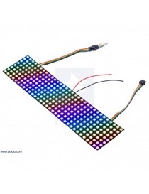
| Addressable RGB 8×32-LED Flexible Panel, 5V, 10mm Grid (APA102C) showing an animated rainbow. |
|---|
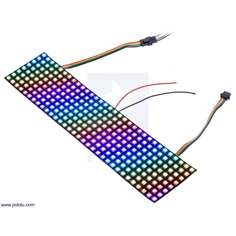
| The connectors and power wires for our APA102C-based LED panels. From left to right: output connector, auxiliary power wires, input connector. |
|---|
Each LED panel has three connection points: the input connector, the auxiliary power wires, and the output connector. These can be seen in the adjacent picture.
The input connector has four male pins inside of a plastic connector shroud, each separated by about 0.1?. The black wire is ground, the green wire is the data signal input (DIN), the yellow wire is the clock signal input (CIN), and the red wire is the power line.
The auxiliary power wires consist of stripped black and red wires. The black wire is ground, and the red wire is the power line. This provides an alternate (and possibly more convenient) connection point for LED matrix power.
The output connector is designed to mate with the input connector of another APA102C LED product to allow the panel to be chained to it. The black wire is ground, the green wire is the data output (DOU), the yellow wire is the clock output (COU), and the red wire is the power line.
All three black ground wires are electrically connected, and all three red power wires are electrically connected.
To control the LED panel from a microcontroller, three wires from the input connector should be connected to your microcontroller. The LED panel’s ground (black) should be connected to ground on the microcontroller, and the LED panel’s data input line (green) and clock input line (yellow) should each be connected to one of the microcontroller’s I/O lines. The male pins inside the input connector fit the female terminations on our premium jumper wires and wires with pre-crimped terminals. If you are connecting the LED panel to a breadboard or a typical Arduino with female headers, you would want to use male-female wires.
We generally recommend powering the LED panel using the auxiliary power wires. Our 5 V wall power adapters work well for powering these LED panels and a DC Barrel Jack to 2-Pin Terminal Block Adapter can help you make the connection between the adapter and the panel. However, you might need a wire stripper to strip off some more insulation from the power wires.
It is convenient that the power wires are duplicated on the input side because you can connect the auxiliary power wires to your 5 V power supply and then the power will be available on the data input connector and can be used to power the microcontroller that is controlling the LED panel. This means you can power the microcontroller and LED panel from a single supply without having to make branching power connections.
Dimensions| Size: | 8 cm × 32 cm |
|---|---|
| Weight: | 65 g |
| Typical operating voltage: | 5 V |
|---|---|
| LEDs: | 256 |
| RGB LED density: | 1 per square centimeter |
| Color: | RGB |
"

Addressable RGB 8x32-LED Flexible Panel, 5V, 10mm Grid (APA102C)