


No products in the cart.

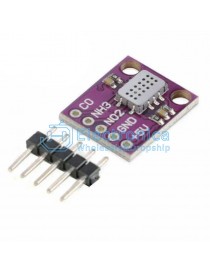
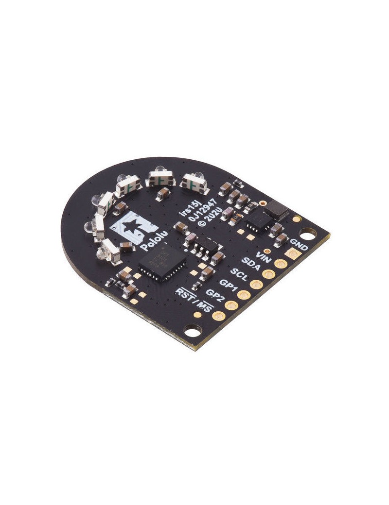
This board is a 3-channel time-of-flight proximity and distance sensor module based on the OPT3101 IC from Texas Instruments. It emits infrared light in one of three selectable directions with its six integrated LEDs and measures distance by measuring the time delay of the reflected signal. Distance measurements can be read through a digital I²C interface. The combined field of view of the three sensing zones is almost 180 degrees, and the maximum range is about one meter. This module does not include any headers
 |
This board is a 3-channel time-of-flight proximity and distance sensor module based on the OPT3101 IC from Texas Instruments. Unlike conventional IR sensors that use the intensity of reflected light to estimate the distance to an object, this board emits 940 nm infrared light pulsed at 10 MHz, and then measures the phase (delay) of the reflected signal, which corresponds to the distance to the target object. It also measures the amplitude of the signal, which indicates how bright/reflective/close the object is.
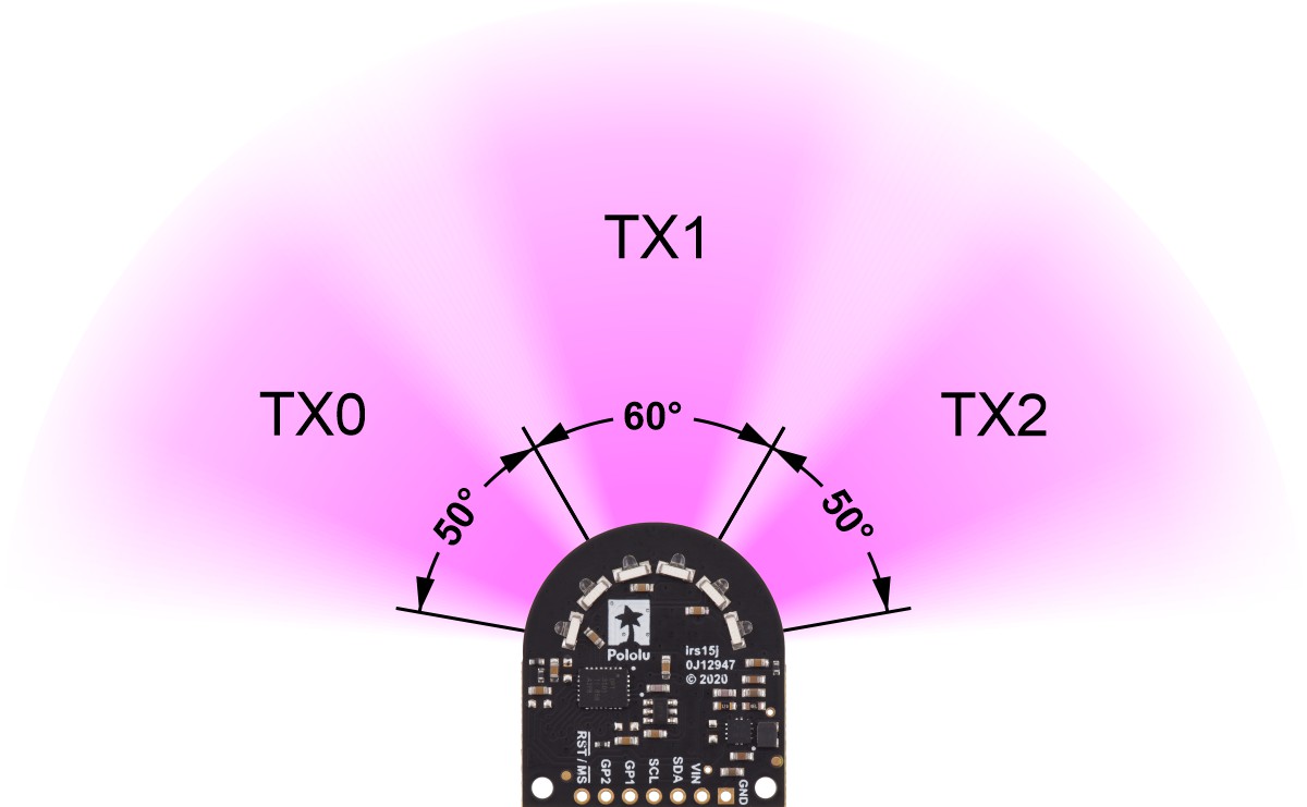
This board has three channels that each cover approximately 50° to 60°, giving the sensor a wide field of view (FOV). In favorable conditions, the sensor can measure objects at distances up to 1 m. Distance measurements are available through the sensor’s I²C interface, which is also used to configure the sensor.
 |
|
Emitter channels and field of view of the 3-channel OPT3101 distance sensor module for TI-RSLK MAX. |
|---|
 |
This module is designed to be mounted onto the 7-pin connector on the front of a TI-RSLK MAX chassis board, but it can be used with any I²C-capable device. The board can be powered from a 2.5 V to 5.5 V supply. On-board regulators supply the 3.3 V logic voltage to the OPT3101. The board includes a circuit that shifts the I²C clock and data lines to the same logic voltage level as the supplied VIN, making it simple to interface the board with 3.3 V or 5 V systems, and the board’s 0.1″ pin spacing makes it easy to use with standard solderless breadboards and 0.1″ perfboards.
This version does not include any headers and ships as shown in the main product picture. We carry an alternate version with headers soldered intended specifically for use with the TI-RSLK MAX.
Four connections are necessary to use the OPT3101 board: GND, VIN, SDA, and SCL. The VIN pin should be connected to a 2.5 V to 5.5 V source, and GND should be connected to 0 volts. The board’s I²C pins (SCL and SDA) should be connected to an I²C bus operating at the same logic level as VIN.
| Pin | Description |
|---|---|
| GND | The ground (0 V) connection for your power supply. Your I²C control source must also share a common ground with this board. |
| VIN | This is the main 2.5 V to 5.5 V power supply connection. |
| SDA | Level-shifted I²C data line: high is VIN, low is 0 V. Pulled up to VIN with a 10kΩ pull-up resistor. |
| SCL | Level-shifted I²C clock line: high is VIN, low is 0 V. Pulled up to VIN with a 10kΩ pull-up resistor. |
| GP1 | Configurable 3.3 V I/O pin. This pin is not level-shifted. |
| GP2 | Configurable 3.3 V I/O pin. This pin is not level-shifted. |
| RST/MS | Input pin that can be used to reset the board or trigger a new sample. (Both of those functions can also be done with I²C.) Pulled up to 3.3 V with a 10kΩ pull-up resistor. This pin is not level-shifted. |