

No products in the cart.

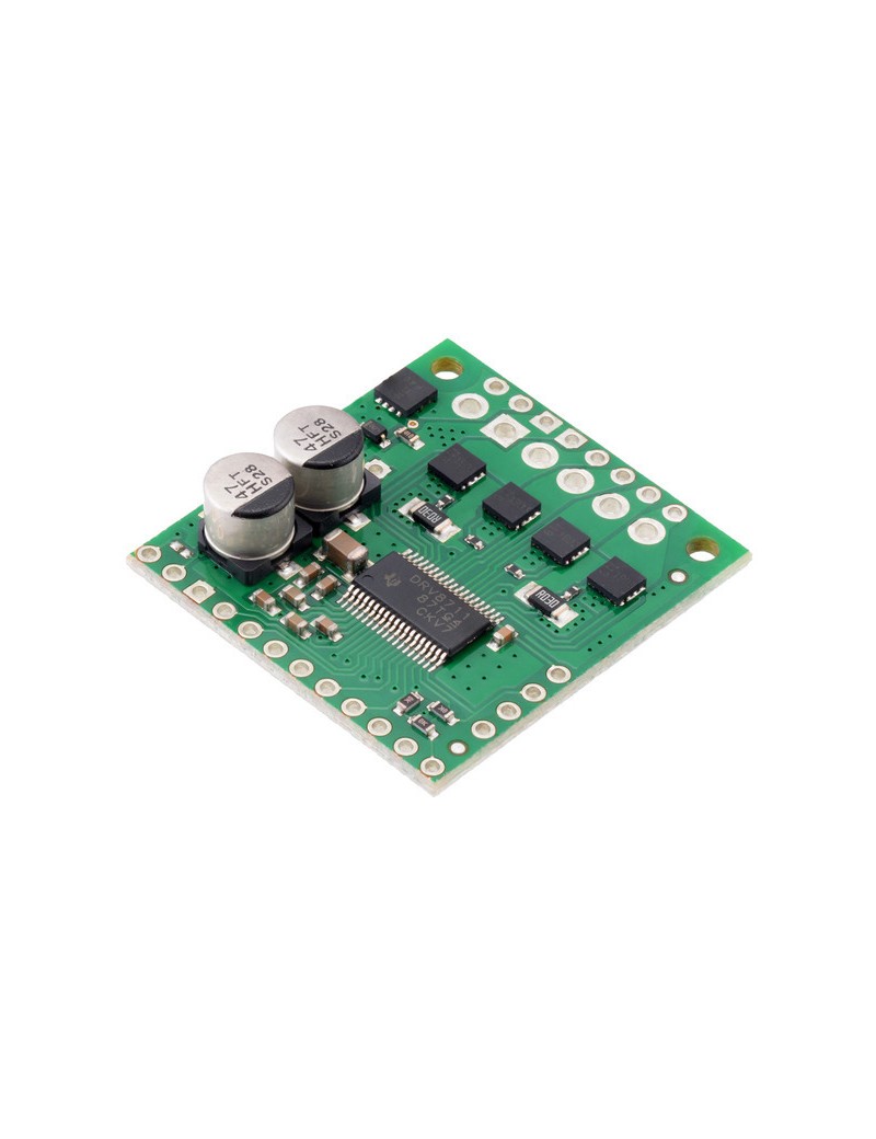
This discrete MOSFET stepper motor driver enables control of one bipolar stepper motor. It supports a wide 8 V to 50 V operating voltage range and can deliver up to 4 A continuous per phase without a heat sink or forced air flow (6 A max with sufficient additional cooling). The SPI interface allows configuration of the current limiting, step mode (9 step modes from full-step through 1/256-step), decay mode, and stall detection. The driver also provides back-EMF feedback that can be used for more advanced control and stall detection algorithms. Additional features include reverse-voltage, under-voltage, and over-current protection.
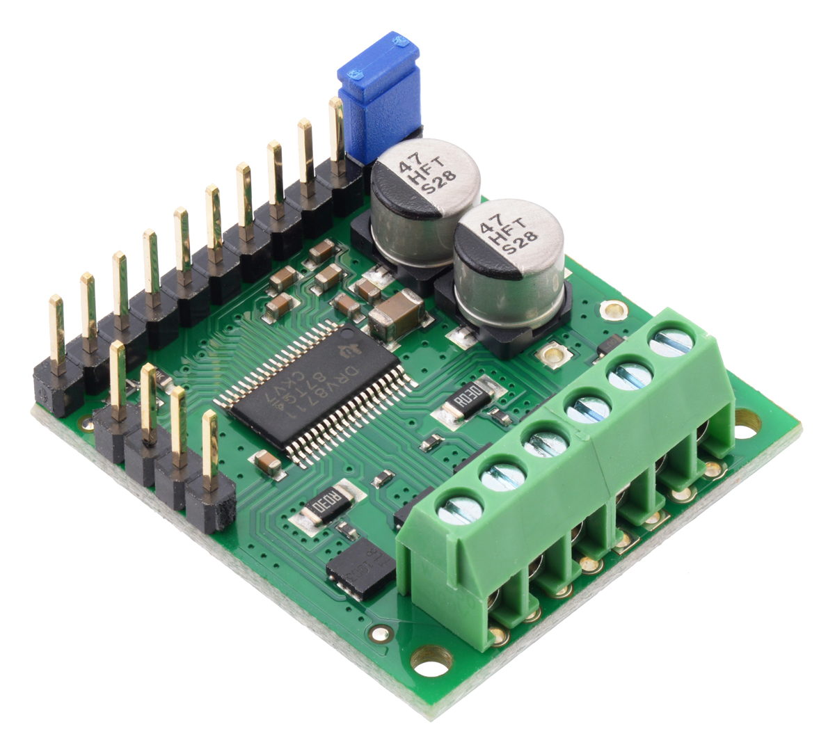
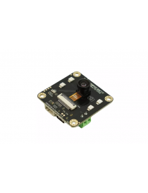
The Pololu High-Power Stepper Motor Driver 36v4 combines the DRV8711 stepper motor driver IC from Texas Instruments with external MOSFETs to enable control of large bipolar stepper motors at operating voltages from 8 V to 50 V. The DRV8711 has many configurable settings, so please see the DRV8711 datasheet for a detailed explanation of its features and how to use them (we also have an Arduino library that simplifies getting started by providing basic functions for configuring and operating the driver).
The driver’s power performance is a function of the external dual H-bridges, which allow the driver to deliver continuous currents up to 4 A per phase without any additional cooling such as heat sinks or forced air flow. (With sufficient additional cooling, the driver can support currents up to around 6 A per phase; see the Power dissipation considerations section below for more information, including important information about using this product safely.)
As an alternative to this stepper motor driver, our Tic 36v4 USB Multi-Interface High-Power Stepper Motor Controller has similar power characteristics and offers high-level interfaces (USB, TTL serial, I²C, analog voltage, quadrature encoder, and RC hobby servo pulses) that make it easier to use for some applications. The Tic’s configuration software allows you to change many of the driver’s settings over USB, eliminating the need to directly use SPI to configure the DRV8711.
19 September 2019 update: We are now shipping a slight revision (md38b) with improved noise and fault tolerance at high input voltages and high current limits.
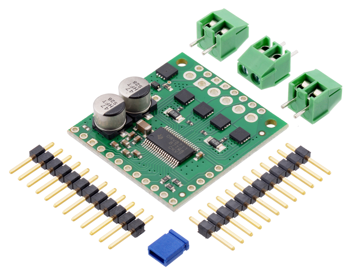
This product ships with all surface-mount components installed as shown in the product picture. However, soldering is required for assembly of the included through-hole parts. The following through-hole parts are included:
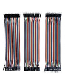
The 0.1″ male headers can be broken or cut into smaller pieces as desired and soldered into the smaller through-holes. These headers are compatible with solderless breadboards, 0.1″ female connectors, and our premium and pre-crimped jumper wires. The terminal blocks can be soldered into the larger holes to allow for convenient temporary connections of unterminated power and motor wires (see our short video on terminal block installation). You can also solder your motor leads and other connections directly to the board for the most compact installation.
|
|
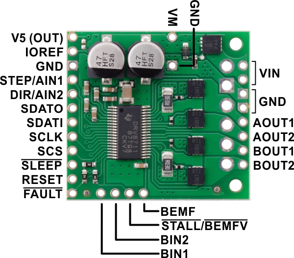 |
For more information about these pins, please refer to the DRV8711 datasheet.
| Size: | 1.3″ × 1.2″ |
|---|---|
| Weight: | 4.9 g1 |
| Minimum operating voltage: | 8 V |
|---|---|
| Maximum operating voltage: | 50 V |
| Continuous current per phase: | 4 A2 |
| Maximum current per phase: | 6 A3 |
| Minimum logic voltage: | 1.5 V |
| Maximum logic voltage: | 5.5 V |
| Microstep resolutions: | full, 1/2, 1/4, 1/8, 1/16, 1/32, 1/64, 1/128, 1/256 |
| Current limit control: | SPI-programmable |
| Reverse voltage protection?: | Y4 |
| Header pins soldered?: | N |
| PCB dev codes: | md38a, md38b |
|---|---|
| Other PCB markings: | 0J12286, 0J12459 |