


arducam
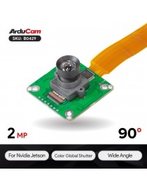
Arducam 2.3MP AR0234...Arducam 2.3MP AR0234 Color Global Shutter Camera for...
143,96 €
Prezzo
No products in the cart.

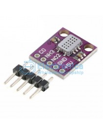
640x480 0.3Mega_x000D_ Pixel VGA CMOS_x000D_ OV7670 Camera_x000D_ Module SCCB_x000D_ compatible for I2C
"
Features
The following schematic diagram show a basic camera based system. The camera module is powered from a single +3.3V power supply. An external oscillator provide the clock source for camera module XCLK pin. With proper configuration to the camera internal registers via I2C bus, then the camera supply pixel clock (PCLK) and camera data (Data[9:0]) back to the host with synchronize signal like HREF and VSYNC.
The host may have integrate camera interface like STM32F2 or STM32F4 series MCUs, or ARM9/11 which has dedicate camera port, and DPS like TI TMS320DM series, as well as FPGAs that user can design special logic for camera application. The typical connection between these system and camera module would show like following diagram.
For the host that doesn’t have a dedicate camera interface, additional hardware is needed. User need to buffer a entire frame before read them out with low speed MCUs. For example ArduCAM shield is a additional hardware that can be connected to Arduino UNO/Mega board, user can take a photo or something like that easily. The following diagram show the system without dedicate camera interface.
| Pin No. | PIN NAME | TYPE | DESCRIPTION |
| 1 | VCC | POWER | 3.3v Power supply |
| 2 | GND | Ground | Power ground |
| 3 | SCL | Input | Two-Wire Serial Interface Clock |
| 4 | SDATA | Bi-directional | Two-Wire Serial Interface Data I/O |
| 5 | VSYNC | Output | Active High: Frame Valid; indicates active frame |
| 6 | HREF | Output | Active High: Line/Data Valid; indicates active pixels |
| 7 | PCLK | Output | Pixel Clock output from sensor |
| 8 | XCLK | Input | Master Clock into Sensor |
| 9 | DOUT9 | Output | Pixel Data Output 9 (MSB) |
| 10 | DOUT8 | Output | Pixel Data Output 8 |
| 11 | DOUT7 | Output | Pixel Data Output 7 |
| 12 | DOUT6 | Output | Pixel Data Output 6 |
| 13 | DOUT5 | Output | Pixel Data Output 5 |
| 14 | DOUT4 | Output | Pixel Data Output 4 |
| 15 | DOUT3 | Output | Pixel Data Output 3 |
| 16 | DOUT2 | Output | Pixel Data Output 2 (LSB) |
ArduCAM provides a full demonstration for OV7670 camera module on Arduino platform. Please download the ArduCAM_OV7670_Camera_Playback.ino from github.
It will turn the ArduCAM into a real digital camera with capture and playback functions.
1. Preview the live video on LCD Screen.
2. Capture and buffer the image to FIFO when shutter pressed quickly.
3. Store the image to Micro SD/TF card with BMP format.
4. Playback the capture photos one by one when shutter button hold on for 3 seconds.
This program requires the latest ArduCAM library and Rev.C or Rev.C+ ArduCAM shield and use Arduino IDE 1.5.2 compiler or above.
"

640x480 0.3Mega_x000D_ Pixel VGA CMOS_x000D_ OV7670 Camera_x000D_ Module SCCB_x000D_ compatible for I2C